Diving Into Jtag Part5
title: Diving into JTAG — Usage Scenarios (Part 5) description: “Some examples of JTAG usage” author: zamuhrishka tags: [arm, cortex-m, mcu, debugging, debugger] —
The main examples of JTAG usage, such as debugging and testing of boards in production, we have considered in the previous parts. And for firmware/embedded developers only the first example - debugging - is the most useful. As far as I know, we almost never encounter the second option, although it can be very useful too. And in this article I want to look at two examples of JTAG Boundary Scan which I think can be very useful in everyday work of a firmware/embedded developer: Bring-up and Revers Enginnering.
Table of Contents
Getting Started
For convenient work you need special software and debugger. In this article I will consider working with the program TopJTAG Probe, and debugger SEGGER J-Link, but it doesn’t mean that only they are suitable for such tasks, just at the moment of writing this article I have them because I am a long-time fan of J-Link debuggers, and TopJTAG Probe program turned out to be the simplest and the most accessible at a quick googling.
While I think many people are familiar with SEGGER products, TopJTAG Probe requires a small description.
TopJTAG Probe program is a software for working with JTAG-interface used for testing printed circuit boards (PCB). This software is commonly used for diagnostics and repair of PCBs, as well as for working with microcontrollers and other devices that support JTAG.
A boundary-scan (JTAG) based simple logic analyzer and circuit debugging software. Provides the ability to monitor pin values in real-time without interference with the normal operation of a working device and to interactively set up pin values for testing of board-level interconnects or on-chip internal logic.
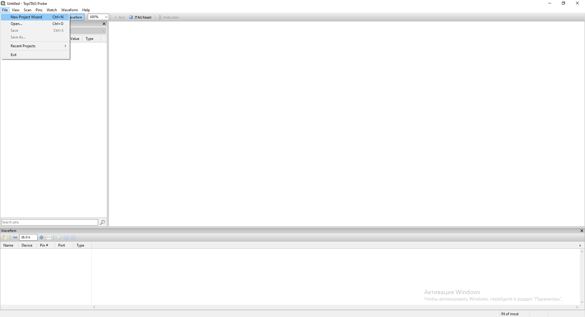
To start working with TopJTAG Probe we need to create a new project. To do this, go to the File->New Project Wizard menu.
In the next window select the required JTAG Probe and frequency. In my case it is SEGGER J-Link and 12 MHz.
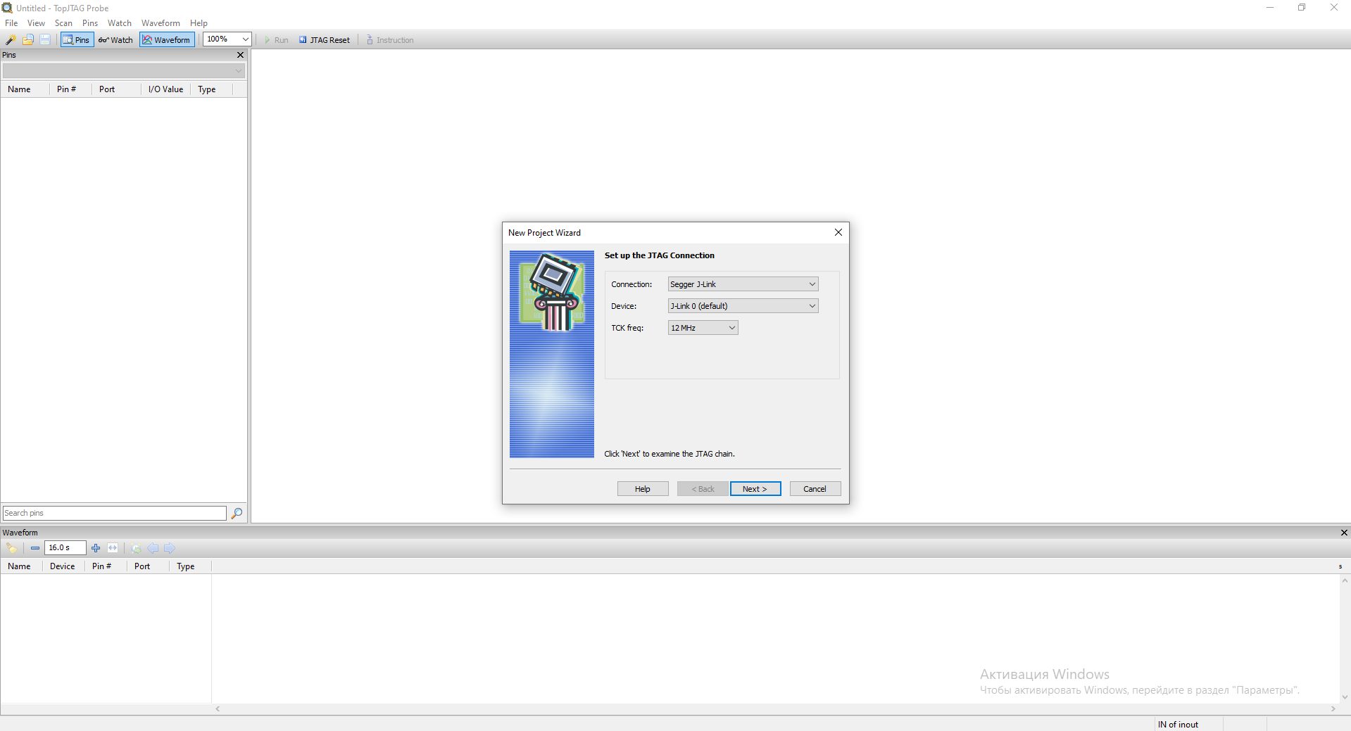
Click Next.
The program will scan our JTAG circuit and display a list of available TAP IDs.
You should already have a debugger connected to the board and to the computer for this step to go well
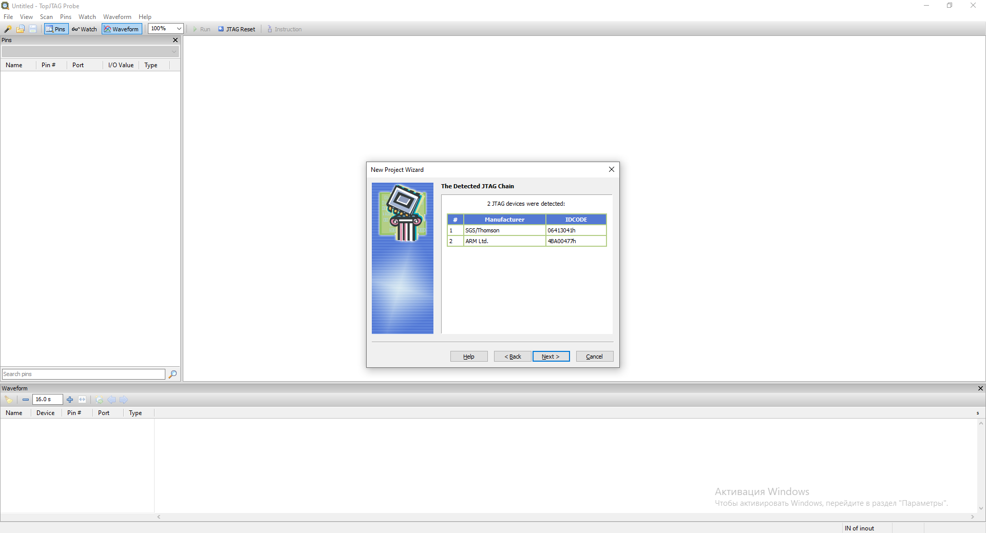
Click Next.
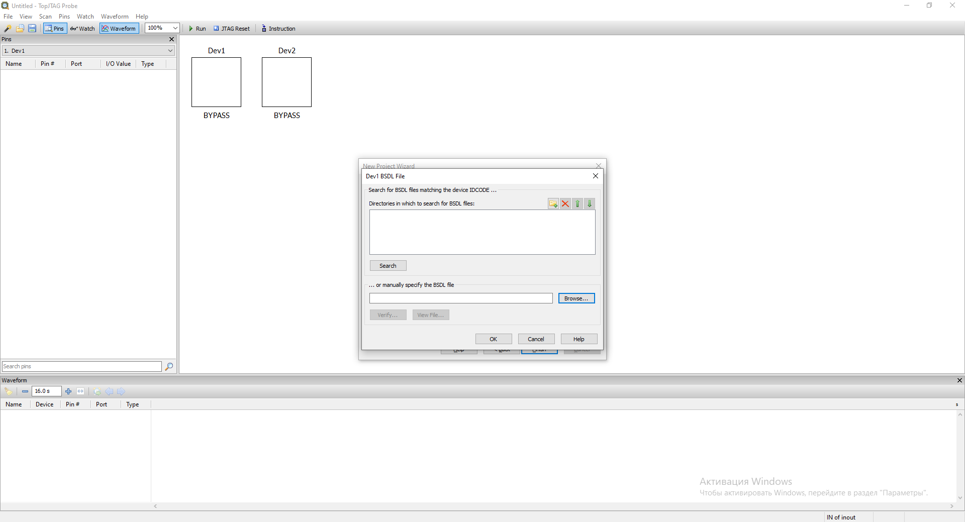
At this point, you must specify .BSD files for each detected TAP. If you do not specify a .BSD file for
a TAP, it will be put into the BYPASS state.
We specify STM32F405_415_407_417_LQFP100.bsd
file for the first TAP - SGS/Thomson(06413041h) as it is responsible for Boundary Scan. We leave the second TAP
in BYPASS. To select a file, click on the CLICK HERE TO SET link and select the desired file.
After that we press Finish and now the program is ready to work.
Appearance of the program:
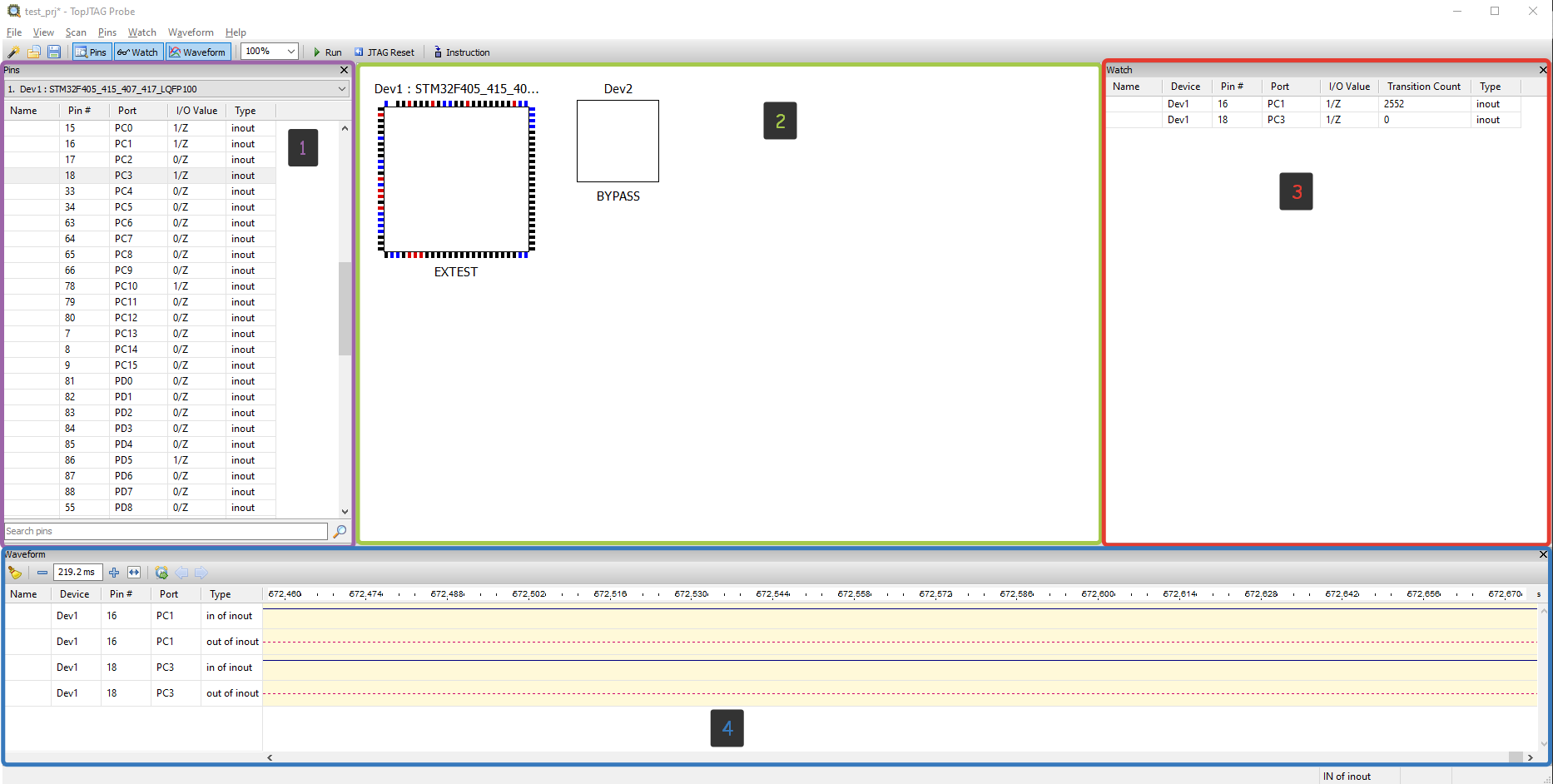
1 - Pins Window. The Pins window lists all pins belonging to the selected device.
Any pin can be quickly located by typing its name, number or port name into the search box.
The pin or bus name, pin number, port name, type and current value are displayed for every pin.
2 - JTAG Chain (Main) View. The JTAG Chain view (main program’s view) shows package outlines
with color-coded pin values. These values are updated while the boundary-scan is running.
A device instruction is displayed below the package outline.
Pin values are color-coded. Black means 0, red — 1, brown — high-Z, and blue — linkage pin. For bidirectional pins it is possible to display either input or output values.
3 - Watch Window. The Watch window keeps pins of interest in one place to simplify monitoring and/or control.
4 - Waveform Window. The Waveform window records and displays waveforms. This is a wonderful tool to view
and analyze a signal’s history. It is particularly useful for fast changing signals.
Board Bring Up
Although assembled PCBs can be tested in production, but in general as far as I know it is not a mandatory procedure. So when these boards come to the Embedded department, especially when it’s the first batch that firmware/embedded developers are going to work with, the boards should be tested to make sure they work properly before they start working on the firmware. Usually (at least that was the case where I worked) this is done by the circuit designer, but since the microcontroller is empty, this check is limited to the test that the board does not burn up when turned on and that the power supply system provides all the necessary voltages.
In some cases, a special test firmware can be prepared specifically for Bring-Up, which either automatically or via CLI interface can enable/disable board modules for testing. In any case, no matter how it happens Bring-Up almost always requires interaction between embedded and circuit designer and additional work to create test firmware.
However, it seems to me that JTAG Boundary Scan can facilitate this work by allowing the circuit designer to control the microcontroller pins and thus perform a better and deeper analysis of the board and not depend on the programmer. And it saves the programmer from having to write special firmware for Bring-Up. All you need for this is a test board, a .BSDL file for the corresponding microcontroller, a debugger and a special program that allows you to control the controller pins through GUI. Also an additional advantage of this approach as I see it is universality, i.e. you don’t need to write a new version of the test firmware for each new microcontroller. And if you remember that Boundary Scan allows you to check the signal integrity for a multiprocessor chain, where processors may have BGA cases and multilayer boards and it may be very difficult to get to the contacts with probes.
So let’s see what is needed for an elementary Bring-Up? To begin with, at least, you need to be able to control the microcontroller pins (set to logic one/logic zero) and read the state in which the microcontroller pin is located and JTAG allows you to do this, and programs like TopJTAG Probe allow you to do it more or less conveniently.
As a board for Bring-Up I will use already familiar from the previous parts STM32F407G-DISC1 with microcontroller STM32F407VG.
GPIO output control
Let’s try to control the LEDs on our board. Quite a workable task for Bring-Up, I think. So we know that the
LEDs are connected to pins: PD12, PD13, PD14, PD15. They are turned on by setting the pin to a logic
one, and turned off by a logic zero, respectively. To select the required level on a pin, it is necessary to
find this pin in the Pin window and select the necessary actions from the context menu:
Controlling LEDs on STM32DISCO board using JTAG Boundary Scan
GPIO input state view
Another necessary operation that is required for such a Bring-Up is to view the state of the chip pin. This can also be done using JTAG Boundary Scan and TopJTAG application. You can view the output state either in the Watch window or in the Waveform window. Let’s look at the state of the output to which the button is connected:
Check GPIO input state using JTAG Boundary Scan
Note: that as mentioned in the article Diving into JTAG. Part 3 - Boundary Scan there can be several scan cells per pin and here you can see that there are two of them: one for receiving and one for transmitting. And as you can see that when the controller transmits something, the receiving scan cell duplicates this signal, as seen in the video with LEDs, but if the output works only for receiving, the signal is present only on one cell, as seen in the video with the button.
Revers Enginnering
One of the interesting things is that the SAMPLE instruction does not affect the firmware in any way, which
means that you can use it for a kind of logic analyzer actually built into the controller. Where can it be useful?
For example, when you don’t have an oscilloscope or analyzer at hand. And, as it seems to me, this function can be
useful when Revers Enginnering a board, especially microchips with BGA-type packages or multilayer boards when it is
difficult to determine with a simple multimeter which pin of the chip is responsible for what and then using the
SAMPLE command can help.
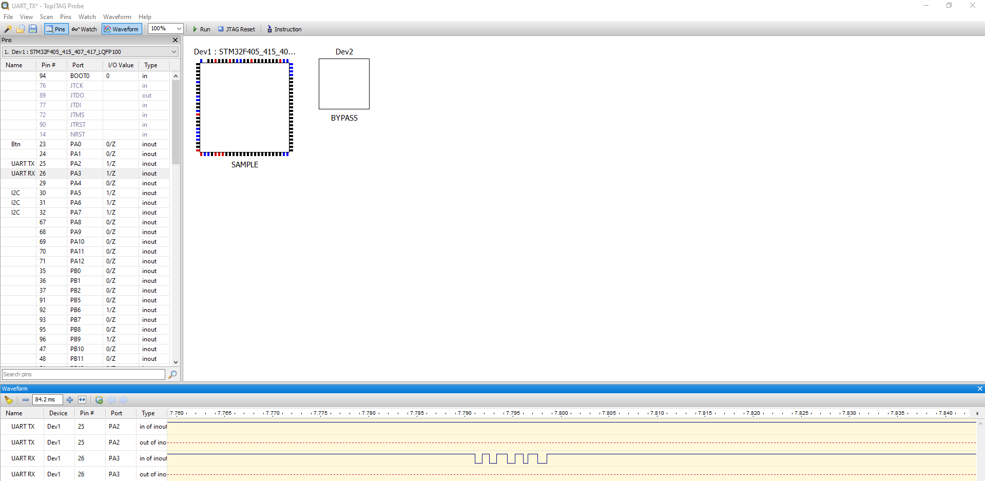
However, this is really a very simple logic analyzer. And while seeing some very simple and low speed signals
(such as controlling LEDs, pressing a button or controlling some load) with this analyzer is quite easy and simple
as shown in the chapter above, when dealing with higher speed protocols the signal that is drawn on the Waveform is
very distorted. Here is an example of how the transmission of the symbol “U” (which has a code equal to 0x55)
through UART at 1200 baud looks like:
and at 2400 baud:
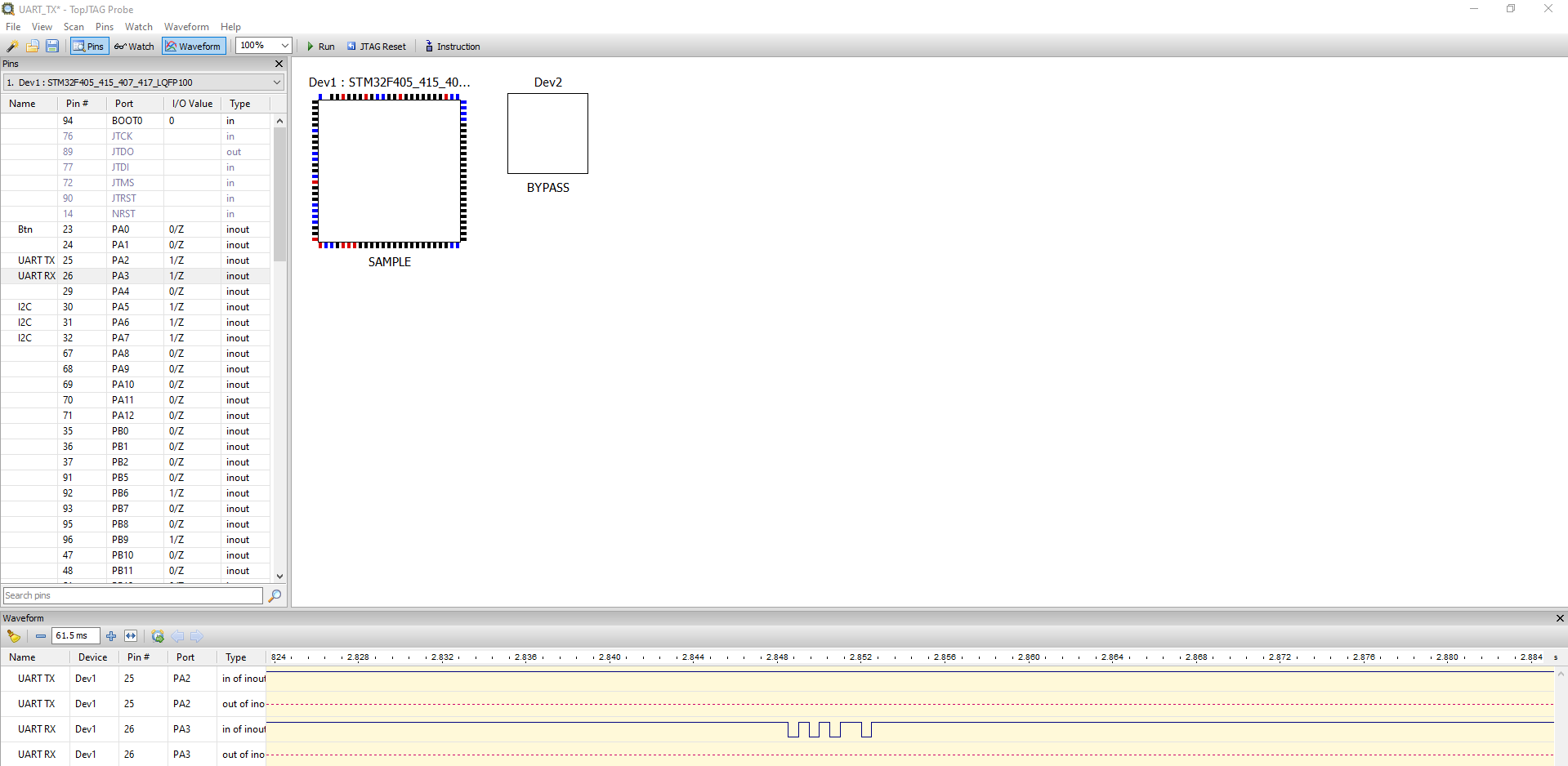
As you can see even at 2400 baud the signal is distorted (2 bits were lost).
And here is how SPI signal looks like with baudrate 250 KBits/sec:
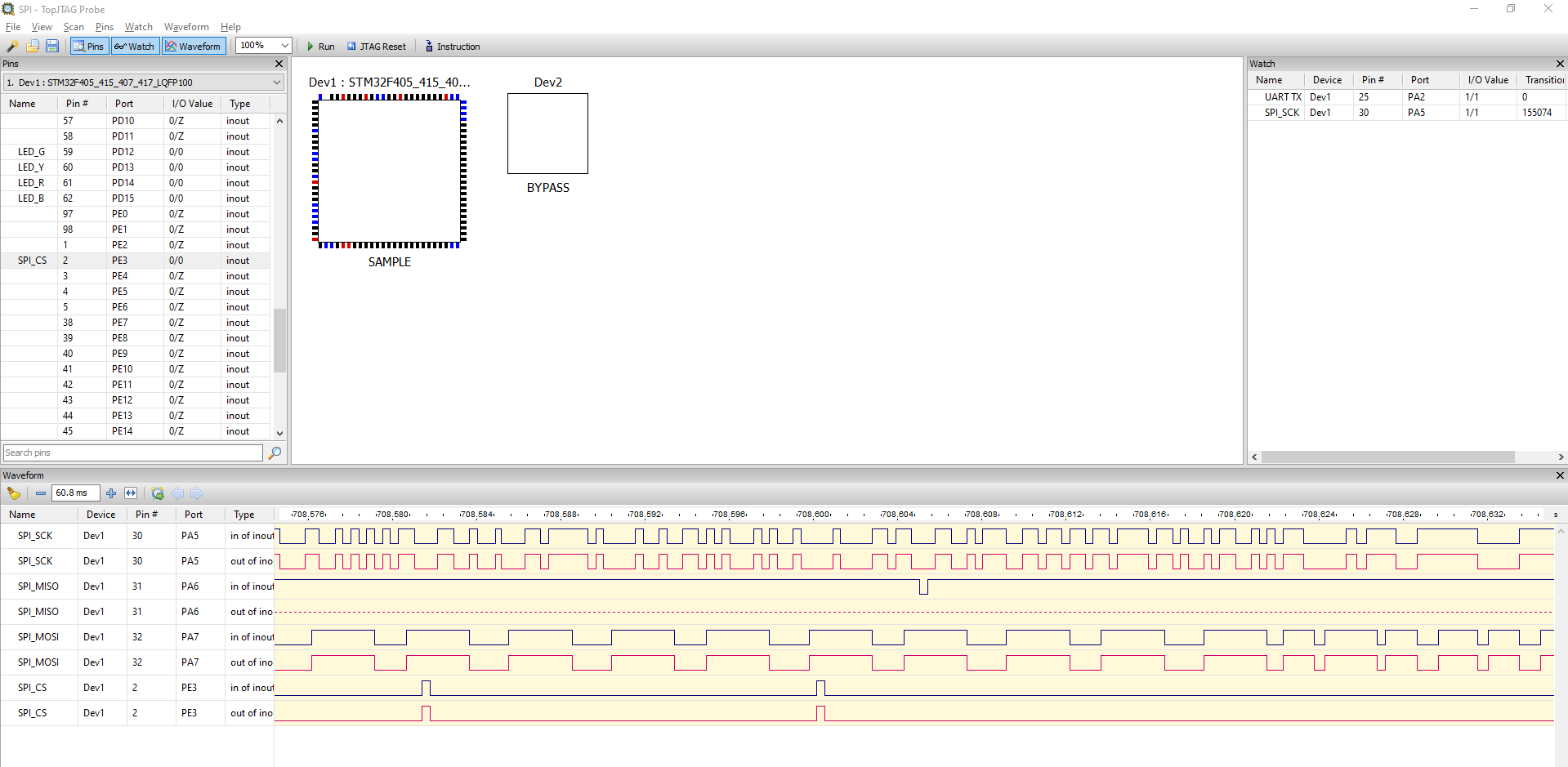
As you can see, it is hard to recognize SPI from this waveform, especially if you look at the SCK signal.
Most likely, the impossibility to analyze higher speed signals in this way is rooted in the limitations of the software and debugger that I use, because they are simply not designed for such a task. And maybe there are software and hardware for this purpose somewhere, but unfortunately they are not available to me.
However, despite such limited use of this functionality, it can still be useful in some specific cases: you can see which pins of the controller are alive and functioning at all or analyze the logic of the firmware, for example on this example:
Simple and bad Logic Analyzer based on JTAG Boundary Scan
You can see that after we press the button - communication starts on some protocol and although it is difficult to understand it from the signal, but it is SPI protocol.
Conclusion
In this article I have tried to expand the area of JTAG usage a little bit. It is possible that the given examples are rare in real life, but nevertheless they may be useful for someone. At least for Bring-up and board repair I will definitely use JTAG Boundary Scan now. :)
In the next article (most likely the final one) we will dive a bit into the security issue related to JTAG: we will consider ways to restrict access to the JTAG interface and also ways to bypass these restrictions.
Note: This article was originally published by Aliaksandr on his blog. You can find the original article here.
See anything you'd like to change? Submit a pull request or open an issue on our GitHub